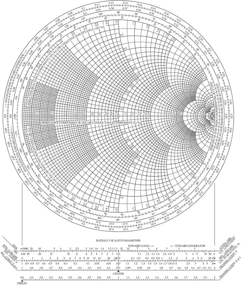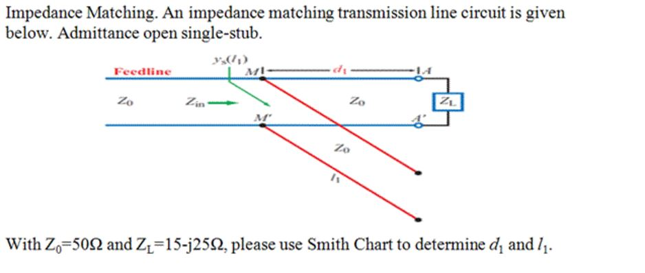
Several alternatives are possible when trying to match a load (or a generator) to the reference impedance of a transmission line. The open-circuit stub location in wavelengths from the amplifier load interface is a function of the clockwise angular difference between point "A" and GammaL. Smith chart is very useful when designing matching networks. The Smith chart is a chart of normalized impedances (or admittances) in the complex reflection coefficient plane. 'BackgroundColor', 'Position',)Īnnotation(container, 'arrow',) Calculate the Stub Location and the Stub Length for the Output Matching Network 'HorizontalAlignment', 'center', 'FontSize',8. These reflection coefficients are measured at the amplifier interfaces.Ĭircle(amp,freq, 'Gamma',abs(GammaL),hsm) Calculate and Plot the Complex Load and Source Reflection CoefficientsĬalculate and plot all complex load and source reflection coefficients for simultaneous conjugate match at all measured frequency data points that are unconditionally stable. This example uses the YZ Smith chart because it's easier to add a stub in parallel with a transmission line using this type of Smith chart.

Smith chart impedance matching network designs have been presented in the course lecture. It also makes it easy to calculate transmission line impedance and length by graphical means. transmission lines and discrete inductances and capacitances. You dont need a Smith Chart to do impedance matching, although it does make it easier. A Smith Chart is simply a method of displaying S Parameters. At this location, the stub will negate the transmission line susceptance, resulting in a conductance that equals the load or source terminations. You can still plot S parameters, just not on a Smith Chart. Figure 2: Input impedance Zin j Z i n j of a 3 8 3 8 open transmission line. The input impedance is purely inductive Zin j Z i n j. The Smith chart is used even though the characteristic impedance normalizing factor is unknown. On the Smith Chart, we start from the load impedance and add a 0.375 0.375 line, following the WTG scale.

use a smith chart for impedance matching in the case of transmission lines and. Transmission Line Impedance Matching Using the Smith Chart (Letters) Abstract: A graphical computation method is described for transforming complex load impedances into resistive load impedances using transmission line matching sections. Mysteries of the Smith Chart - Transmission Lines, Impedance Matching. This Article Has Provided a Clear Description On Smith Chart, Its Types.

Movement along a transmission line is equivalent to traversing a circle centered at the origin of the Smith chart with radius equal to a reflection coefficient magnitude.Ī single transmission line stub can be inserted at the point on a transmission line when its admittance (transmission line) intersects the unity conductance circle. The Smith Chart was originally created many years ago as an RF engineering aid. The center of the Smith chart represents a normalized source or load immittance. Now, if we use a transmission line section to rotate the impedance on the Smith Chart until it intersects the Rez1 circle, then we can exactly match any.


 0 kommentar(er)
